


BRAIN WAVE MONITOR
To get ready to make your own Portable Brain Wave Monitor all you need is about 40 bucks and a bit a time and ingenuity. Take a look at our work and see if you can’t make one of your own!
Materials:
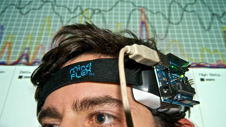
1 MindFlex – $25.00: eBay is one of the best places to find!
1 Arduino Uno R3 – $15.00: Find it on the Aruino site here!
1 Mini Breadboard: The “bread and butter” of electrical engineering.
1 SainSmart 1.8 ” Color TFT Display – Now you can see what you’re doing!
Some Wires: Go “Office Space” on your printer and salvage the wires.
A PC or Laptop: It’s 2016, everyone has one. Right?
Software & Files:
Arduino GUI <= Download Right Here!
Arduino Brain Example Code <= Download at the bottom!
Tools:
Soldering Iron: Every maker should have one.
Hot Glue Gun: Your mom should have one you can borrow from Arts and Crafts time!
Drill: Not really needed, but who doesn’t love to play with power tools?
Other Tools: Pliers, Wire Cutters, Wire Strippers, etc.
MONITOR SETUP
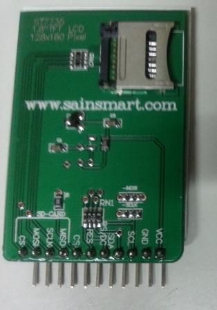
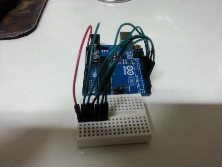
Use the mini breadboard to connect the display to the Arduino. Use jumper wires to connect from the Arduino pins to the breadboard in the following order:
Arduino: 5v TFT DISPLAY VCC
gnd GND
Digital 4 SCL
5 SDA
6 CS
7 DC
8 RES
In order to test the display, you will need to download and install two libraries into your Arduino IDE. Although the display is sold by Sainsmart, I had trouble using their libraries and downloaded the libraries from ADAFRUIT, who sells a similar display and has much better documentation and support..I’d normally feel a little guilty about ordering these from SainSmart and using the Adafruit instructions and libraries, but I purchase enough other stuff from Adafruit to appease my conscience. If you end up taking the same route I did, I encourage you to at least look at the other stuff they offer.
Two libraries need to be downloaded and installed: The first is the ST7735 library (which contains the low-level code specific to this device). The second is the Adafruit GFX Library (which handles graphics operations common to many displays that Adafruit sells). Download both ZIP files, uncompress and rename the folders to ‘Adafruit_ST7735’ and ‘Adafruit_GFX’ respectively, place them inside your Arduino libraries folder and restart the Arduino IDE.
You should now be able to see the library and examples in select File > Examples > Adafruit_ST7735 > graphicstest sketch. load the sketch to your Arduino.
If you were successful at installing the libraries, and loading the graficstest sketch, Click on the verify button to compile the sketch and make sure there are no errors.
It’s time to connect your Arduino to your PC using the USB cable, and click on the upload button to upload the sketch to the Arduino.
Once uploaded, the Arduino should perform all the test display procedures! If you’re not seeing anything – check to see if the back-light is on, if the back-light is not lit, something is wrong with the Power wiring. If the back-light is lit ,but you see nothing on the display recheck the digital signals wiring.
If everything is working as expected, we are ready to wire up the DHT sensor.
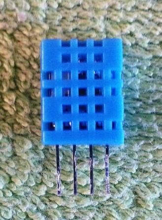
As with the display, I used jumper wires to connect the required power and data pins for the DHT11 using the mini Breadboard. Line up the pins and then plug in the sensor.
Looking at the front of the sensor:
From Left to Right connect pin 1 of DHT11 to 5 V, Pin 2 to Digital Pin 2 of the Arduino, Pin 3 no connection, and Pin 4 to Arduino GND.
You need to download another Library to get the Arduino to talk with the DHT11 sensor. The sensor I got didn’t come with any documentation, so I Googled around until I found a library that works.
I found it in the Virtualbotix website
As with the display libraries, Download the library unzip it, and install it in the Arduino IDE. Place it inside your Arduino libraries folder , rename it DHT11, and restart the Arduino IDE.
You should now be able to see the library and examples in select File > Examples > DHT11 > dht11_functions sketch.
oad the sketch to your Arduino.
If you were successful at installing the libraries, and loading the dht11_functions sketch, Compile the sketch by clicking on the verify button and make sure there are no errors.
It’s time to connect your Arduino to your PC using the USB cable. Click on the upload button to upload the sketch to the Arduino.
Once uploaded to the Arduino, open the serial monitor, and you should see the data stream with information coming from the sensor.
If you got the sensor working, we’re now ready to display the data on the TFT Screen..
// copy the sketch below and paste it into the Arduino IDE compile and run the program.
// this sketch was created using code from both the adafruit and the virtuabotix sample sketches
// You can use any (4 or) 5 pins
#define sclk 4
#define mosi 5
#define cs 6
#define dc 7
#define rst 8 // you can also connect this to the Arduino reset
#define ANALOG_IN 0 // for cds light sensor
#include <Adafruit_GFX.h> // Core graphics library
#include <Adafruit_ST7735.h> // Hardware-specific library
#include <SPI.h>
#include <dht11.h> // dht temp humidity sensor library
dht11 DHT11;
Adafruit_ST7735 tft = Adafruit_ST7735(cs, dc, mosi, sclk, rst);
void setup(void) {
DHT11.attach(2); // set digital port 2 to sense dht input
Serial.begin(9600);
Serial.print(“hello!”);
tft.initR(INITR_BLACKTAB); // initialize a ST7735S chip, black tab
Serial.println(“init”);
//tft.setRotation(tft.getRotation()+1); //uncomment to rotate display
// get time to display “sensor up time”
uint16_t time = millis();
tft.fillScreen(ST7735_BLACK);
time = millis() – time;
Serial.println(time, DEC);
delay(500);
Serial.println(“done”);
delay(1000);
tftPrintTest();
delay(500);
tft.fillScreen(ST7735_BLACK);
// Splash screen for esthetic purposes only
// optimized lines
testfastlines(ST7735_RED, ST7735_BLUE);
delay(500);
testdrawrects(ST7735_GREEN);
delay(500);
tft.fillScreen(ST7735_BLACK);
}
void loop() {
// tft.invertDisplay(true);
// delay(500);
// tft.invertDisplay(false);
tft.setTextColor(ST7735_WHITE);
tft.setCursor(0,0);
tft.println(“Sketch has been”);
tft.println(“running for: “);
tft.setCursor(50, 20);
tft.setTextSize(2);
tft.setTextColor(ST7735_BLUE);
tft.print(millis() / 1000);
tft.setTextSize(1);
tft.setCursor(40, 40);
tft.setTextColor(ST7735_WHITE);
tft.println(“seconds”);
tft.setCursor(0, 60);
tft.drawLine(0, 50, tft.width()-1, 50, ST7735_WHITE); //draw line separator
tft.setTextColor(ST7735_YELLOW);
tft.print(“Temperature (C): “);
tft.setTextColor(ST7735_GREEN);
tft.println((float)DHT11.temperature,1);
tft.setTextColor(ST7735_WHITE);
tft.print(“Humidity (%): “);
tft.setTextColor(ST7735_RED);
tft.println((float)DHT11.humidity,1);
tft.setTextColor(ST7735_YELLOW);
tft.print(“Temperature (F): “);
tft.setTextColor(ST7735_GREEN);
tft.println(DHT11.fahrenheit(), 1);
tft.setTextColor(ST7735_YELLOW);
tft.print(“Temperature (K): “);
// tft.print(” “);
tft.setTextColor(ST7735_GREEN);
tft.println(DHT11.kelvin(), 1);
tft.setTextColor(ST7735_WHITE);
tft.print(“Dew Point (C): “);
tft.setTextColor(ST7735_RED);
tft.println(DHT11.dewPoint(), 1);
tft.setTextColor(ST7735_WHITE);
tft.print(“DewPointFast(C): “);
tft.setTextColor(ST7735_RED);
tft.println(DHT11.dewPointFast(), 1);
tft.drawLine(0, 110, tft.width()-1, 110, ST7735_WHITE);
tft.setCursor(0,115);
tft.print(“Light intensity “);
int val = analogRead(ANALOG_IN);
tft.setCursor(60, 130);
tft.setTextColor(ST7735_YELLOW);
tft.println(val, 1);
delay(2000);
tft.fillScreen(ST7735_BLACK);
}
void tftPrintTest() {
tft.setTextWrap(false);
tft.fillScreen(ST7735_BLACK);
tft.setCursor(0, 60);
tft.setTextColor(ST7735_RED);
tft.setTextSize(2);
tft.println(“temperature”);
tft.setTextColor(ST7735_YELLOW);
tft.setTextSize(2);
tft.println(“humidity”);
tft.setTextColor(ST7735_GREEN);
tft.setTextSize(2);
tft.println(“monitor”);
tft.setTextColor(ST7735_BLUE);
//tft.setTextSize(3);
//tft.print(3598865);
delay(500);
}
void testfastlines(uint16_t color1, uint16_t color2) {
tft.fillScreen(ST7735_BLACK);
for (int16_t y=0; y < tft.height(); y+=5) {
tft.drawFastHLine(0, y, tft.width(), color1);
}
for (int16_t x=0; x < tft.width(); x+=5) {
tft.drawFastVLine(x, 0, tft.height(), color2);
}
}
void testdrawrects(uint16_t color) {
tft.fillScreen(ST7735_BLACK);
for (int16_t x=0; x < tft.width(); x+=6) {
tft.drawRect(tft.width()/2 -x/2, tft.height()/2 -x/2 , x, x, color);
}
}
HARDWARE (MINDFLEX) SIDE
Lets start with the EEG Monitor – but before attempting to start this phase, I recommend you visit the Frontier Nerds web site, where they do a better job than I could, of explaining how to mod the MindFlex headset so you can interface it with the arduino.
1 – Remove the 4 screws from the back cover of the left pod of the Mind Flex headset.(The right pod holds the batteries.)
2 – Open the case to expose the electronics.
3 – Identify the NeuroSky Board.It is the small daughterboard towards the bottom of the left pod.
4 – If you look closely, you will see pins that are labeled T and R — these are the pins the EEG board uses to communicate serially to the microcontroller on the main circuit board.
5 – Solder a length of wire (carefully) to the “T” pin. I used a pair of wires that came from an old PC. Be careful not to short the neighboring pins.
6 – Solder another length of wire to ground using the large solder pad where the battery’s ground connection is.
7 – Drill a hole in the case for the two wires to poke through after the case was closed.
8 – Guide the wires through the hole, and recheck your soldering. I recommend putting a dab of glue in the hole to secure the wires in place ( I used my hot glue gun to do this).
9 – Carefully put the back case back on and re secure the screws.
10 – Connect the Mind Flex to the Arduino; Connect the Wire coming from the T pin to the Arduino rx pin; Connect the other wire to an arduino GND pin.
SOFTWARE SIDE
Initial software test to make sure your mind Flex is talking to the Arduino: Run the example BrainSerialOut sketch.
Note: You will not need the Mini display for this test, and if you have it connected nothing will display on it yet.
1.- You will need to download and install the Brain Library from the frontiernerds web site.Decompress the zip file and drag the “Brain” folder to the Arduino’s “libraries” folder inside your sketch folder. Restart the Arduino IDE.
You should now be able to see the library and examples in select File > Examples > Brain > BrainSerialOut sketch.
If you were successful at installing the libraries, and loading the BrainSerialOut sketch, Click on the verify button to compile the sketch and make sure there are no errors.
It’s time to connect your Arduino to your PC using the USB cable, and click on the upload button to upload the sketch to the Arduino.
Plug the two wires that you put in the Mind flex headset to the Arduino: the T signal wire from the mind flex to the rx pin in the Arduino; The ground wire from the Mind flex headset to the Arduino gnd pin.
Once the sketch is uploaded to the Arduino, make sure your Mind flex headset is connected to the Arduino, and turn it on. Open the serial monitor.You should see a stream of coma separated numbers scrolling by.
NOTE: If the sketch doesn’t upload and you get a message like the one below,
avrdude: stk500_getsync(): not in sync: resp=0x00
Disconnect the wire from the arduino rx pin, it sometimes interferes with the upload process.
Note that the connection to the Neurosky headset is half-duplex — it will use up the rx pin on your Arduino, but you will still be able to send data back to a PC via USB. (Although in this case you won’t be able to send data to the Arduino from the PC.)
Once disconnected click on the upload button again and, if successful, reconnect the wire to the rx pin.
READING BRAINWAVES
Before we proceed to the next part (sketch), you should know a couple of hints if you’re running into trouble:
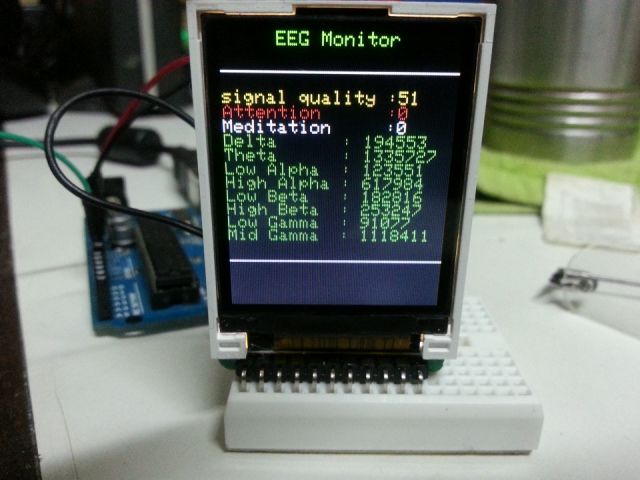
1 – If the signalquality is anything but 0, you will not get a meditation or attention value.
2 – The values for the brain waves( Alpha, Beta, Gamma, etc… ) are kind of nonsensical. They still change value even if the signal quality is greater than zero! Also if you place any finger on the forehead sensor and another one on the ear sensor on the left pad, you still get readings for all the brain wave functions. I mention this because I’m not quite sure whether the values are actually very reliable. In any case, the only values that are usable, if you want to control something with your brain are the Attention and Meditation.
Alright, so here’s the code:
// Copy and Paste the sketch below to your ardunio IDE .
#define sclk 4
#define mosi 5
#define cs 6
#define dc 7
#define rst 8
#include <Adafruit_GFX.h> // Core graphics library
#include <Adafruit_ST7735.h> // Hardware-specific library
#include <SPI.h>
#include <Brain.h>
Adafruit_ST7735 tft = Adafruit_ST7735(cs, dc, mosi, sclk, rst);
Brain brain(Serial);
void setup(void) {
tft.initR(INITR_BLACKTAB); // initialize a ST7735S chip, black tab
tftPrintTest(); //Initial introduction text,
delay(1000);
tft.fillScreen(ST7735_BLACK); // clear screen
tft.setTextColor(ST7735_WHITE);
tft.setTextSize(1);
tft.setCursor(30,0);
tft.println(“EEG Monitor”);
Serial.begin(9600);
}
void loop() {
if (brain.update()) {
if (brain.readSignalQuality() > 100) {
tft.fillScreen(ST7735_BLACK);
tft.setCursor(0,30);
tft.setTextColor(ST7735_RED,ST7735_BLACK);
tft.println(“signal quality low”);
}
else {
tft.setCursor(30,0);
tft.println(“EEG Monitor”);
tft.drawLine(0, 20, tft.width()-1, 20, ST7735_WHITE);
tft.drawLine(0, 130, tft.width()-1, 130, ST7735_WHITE);
tft.setCursor(0, 30);
tft.setTextColor(ST7735_YELLOW,ST7735_BLACK);
tft.print(“signal quality :”);
tft.print(brain.readSignalQuality());
tft.println(” “);
tft.setTextColor(ST7735_RED,ST7735_BLACK);
tft.print(“Attention :”);
tft.print(brain.readAttention());
tft.println(” “);
tft.setTextColor(ST7735_WHITE,ST7735_BLACK);
tft.print(“Meditation :”);
tft.print(brain.readMeditation());
tft.println(” “);
tft.setTextColor(ST7735_GREEN,ST7735_BLACK);
tft.print(“Delta : “);
tft.print(brain.readDelta());
tft.println(” “);
tft.print(“Theta : “);
tft.print(brain.readTheta());
tft.println(” “);
tft.print(“Low Alpha : “);
tft.print(brain.readLowAlpha());
tft.println(” “);
tft.print(“High Alpha : “);
tft.print(brain.readHighAlpha());
tft.println(” “);
tft.print(“Low Beta : “);
tft.print(brain.readLowBeta());
tft.println(” “);
tft.print(“High Beta : “);
tft.println(brain.readHighBeta());
tft.print(“Low Gamma : “);
tft.print(brain.readLowGamma());
tft.println(” “);
tft.print(“Mid Gamma : “);
tft.print(brain.readMidGamma());
tft.println(” “);
}}
}
void tftPrintTest() {
tft.setTextWrap(false);
tft.fillScreen(ST7735_BLACK);
tft.setCursor(0, 10);
tft.setTextColor(ST7735_WHITE);
tft.setTextSize(1);
tft.println(“INSTRUCTABLES.COM”);
delay(500);
tft.setCursor(40, 60);
tft.setTextColor(ST7735_RED);
tft.setTextSize(2);
tft.println(“EEG”);
tft.setTextColor(ST7735_YELLOW);
tft.setCursor(20, 80);
tft.println(“Monitor”);
tft.setTextColor(ST7735_BLUE);
delay(50);
}